Geophysical laboratory

")
")
Surface geophysics in geotechnics encompasses a set of non-destructive methods used to explore the subsurface first few tens of meters. It plays a crucial role in site investigation prior to construction works by providing information on the nature, structure, and mechanical state of soils. These techniques complement traditional drilling techniques by offering a comprehensive and continuous view of the subsurface; thereby facilitating decision-making in civil engineering.
THERMAL CONDUCTIVITY
Thermal conductivity (λ) is a material-specific characteristic. It indicates the amount of heat flux through thermal conduction.
The LTPS’s department of geophysical tests has the following equipment:
- CRU01 monitoring and reading unit branded Hukseflux
- Thermal Sensors;
- TP09 heating probe;
- An LN01 lance (1.5 m);
- High-performance processing and interpretation software (Hukseflux CRU01); The thermal conductivity method is applied in:
- Measuring soil thermal conductivity and resistivity;
Scope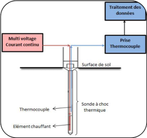
Measuring soil thermal conductivity is performed using a thermal shock probe. It consists of two parts:
• A cylindrical resistive element in which a constant amount of heat is dissipated by the Joule effect throughout the measurement;
• A temperature calculation probe placed at the soil-probe interface.
Insitu tests
")
")
Laboratory tests

")
Electrical Prospecting
")


Electrical prospecting methods are used to determine soil properties by measuring their resistivity ρ (Ohm.m).
The LTPS’s department of Special Tests has the following electrical equipment:
• Terrameter LS, branded ABEM (2500 mA, 250 W, 600 V);
• 4 coils for electrical tomography (64 electrodes, spaced up to 10 meters);
• 4 coils for vertical electrical sounding;
• High-performance processing software (RES2DINV, RES3DINV)
The investigation depth depends on the device used and the nature of the terrain.
It is applied in :
-
Geotechnical investigations and soil studies;
-
Grounding;
-
Water resource studies;
-
Cathodic protection;
SCOPE
The measurement principle is broken down into three steps:
1/ Injection of a current i: from the electrical source through the injection electrodes (A, B);
2/ Measurement of the potential difference DV: between the measuring electrodes (M, N);
3/ Calculation of the apparent resistivity ra: derived from Ohm's law.

DIFFERENT TECHNIQUES
Vertical Electrical Sounding
")
Depth variation of resistivity
Electrical Dragging
")
Lateral variation of resistivity (Iso-resistivity map)
Electrical Tomography
")
Lateral and depth variation of resistivity
TDEM Electromagnetic Prospecting

The time-domain electromagnetic (TDEM) method allows for the reconstruction of the actual resistivity distribution of the subsurface at up to 300-400 m depth.
The LTPS department of Special Tests has the following electrical equipment:
• Walk TEM 2 RX unit branded ABEM;
• Walk TEM 2 20 A TX transmitter branded ABEM;
• 40x40 m transmitter loop;
• RC-200 receiver loop.
The investigation depth depends on the equipment used and the nature of the ground.
PRINCIPLE OF THE METHOD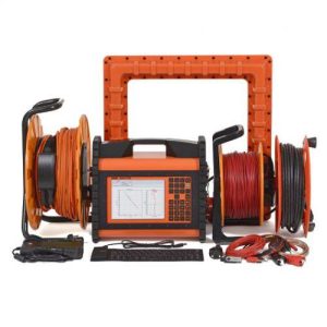
The TDEM method is based on the phenomenon of transient electromagnetic field diffusion. This field is created by the sudden interruption of a current flowing in a transmitting loop. This primary electromagnetic field creates eddy currents in buried conductive objects. These induce a transient secondary magnetic field measured by one or two receiving loops during the interruption.
It is applied in :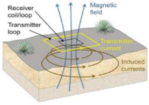
Geotechnical investigations and soil studies.
Groundwater investigation.
Bedrock depth.
Grounding;
Cathodic protection;
Advantages of the TDEM method: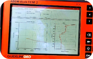
Significant investigation depth.
No contact with the ground (avoiding high soil contact resistance problems).
Good penetration into conductive environments.
Electromagnetic Prospecting


")
Geological radar is a geophysical prospecting method based on the propagation and reflection of electromagnetic waves.
LTPS's department of geophysical tests has the following electromagnetic equipment (Geo Radar):
• SIR-20 unit branded GSSI;
• Antennas of various frequencies
-
Application
Antenna
Investigation depth
Concrete
2.6 GHz
0-0.3 m
Road
2 GHz
0-0.5 m
1 GHz
0-1 m
Geology
400 MHz
0-4 m
200 MHz
0-8 m
100 MHZ
0-20 m
-
Logiciel de traitement très performant (RADAN 6.0) ;
Scope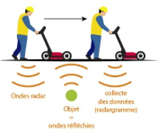
-A transmitting antenna sends very short pulses into the ground or civil structure at frequencies ranging from 16 MHz to 2.6 GHz.
-When waves encounter contact between two horizons with different dielectric permittivities, some of their energy is reflected, while some penetrate more deeply. - A receiving antenna receives the directed, reflected, and refracted waves.
It is applied in :
- Pavement surveying (measuring thicknesses, anomalies, etc.);
- Underground network detection (cables, pipes, metal objects, etc.);
- Archaeology and geology (cavities, basement, etc.);
- Concrete and bridge deck surveying (detection of reinforcement, etc.);
What does Geo Radar measure?
- GPR measures the trip time and amplitude of reflected, transmitted, and/or refracted EM waves between the transmitter and the receiver.
- The amplitude and trip time of EM waves depends on the permittivity and conductivity of the horizon they pass through.
- The amplitude of an EM wave measured at the receiver depends primarily on permittivity contrasts.
Auscultation géologique
")
Auscultation des bétons
")
Auscultation des chaussées
")
Détection des réseaux sous terrain
")
SEISMIC PROSPECTING

Seismic methods are based on the study of ground mechanical wave propagation. Wave propagation velocity depends on the elastic properties of the materials.
The LTPS’s department of Special Tests is equipped with:
• Seismogram branded DAQ Link 3;
• Two 12-track coils (up to 10 meters);
• Downhole well probes;
• Crosshole seismic source;
• processing and interpretation software of High-performance (SeisImager)
The seismic prospecting method is applicable for:
• Determining layer velocities and thicknesses;
• Measuring dynamic moduli;
Scope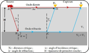
The principle of the seismic method consists of causing a ground tremor using a source (hammer, dynamite, etc.) that creates a vibration wave that propagates in all directions. Then, using geophones, the arrival of some waves (compression, shear, etc.) is recorded.
Different Techniques
LTPS's department of Special Tests offers three different seismic techniques:
• Seismic Refraction
• Downhole
• Crosshole
Sismique Refraction
")
Down Hole
")
Cross Hole
")